10259 Commercial Cooler Fan Control Panel Wiring Diagram
Fan control center wiring diagram. From the (second) a/c relay, connect yellow and orange wires to ground.

Heat pump air conditioner, Capacitor, Electric motor
After repairs, go to step 23).
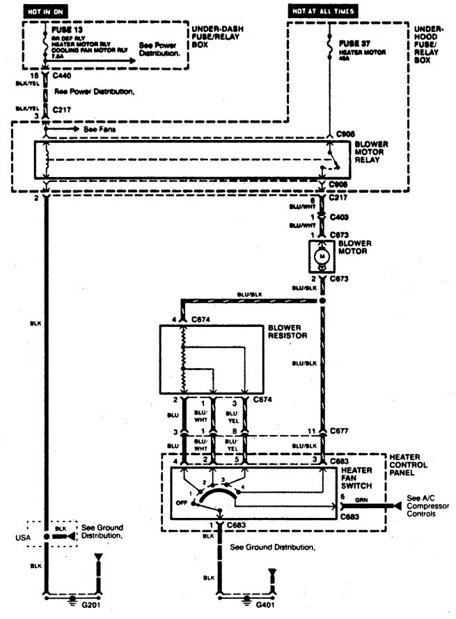
10259 commercial cooler fan control panel wiring diagram. With dual cooling fans, there are two methods for wiring up the relay kit. The electric cooling fans are designed to force air through the Deta electrical wiring diagram offer diagramweb.net.
Relays shown in these diagrams can provide options. (h) and a separate control circuit connected from the Cabling bs en of appropriate type.
Start your wiring project by taking both of the positive wires from the fans and run them to the yellow wires on each relay (tab 87). Image of wiring diagram showing how to wire a thermostatic cooling fan switch to the infinitybox mastercell most ecu's have a trigger that is used to control the cooling fan. 9) check for short to ground in blue wire between pcm and cooling fan relay.
This wiring harness kit is designed to enable simple installation of high performance electric fans. Room air cooler wiring diagram # 1. Electric fan wiring harness nstruction sheet design:
Or a single relay could be used to control both fans. After repairs, go to step 23). This is based on the draw from the fans, if the fans are larger and draw more than 15 amps each, it's recommended to install a second relay kit as shown below.
*cable coloring varies from fan to fan. Installation instructions for the universal thermostatically controlled electric fan relay kit be sure to route wires in a manner so that they do not chafe on any sharp metal edges and use proper terminals and connectors at all connecting points to insure proper electric fan function. 10259 commercial cooler control panel wiring diagram.
The gray wire from the aic relay Rx75 john deere wiring diagram; Located in the battery junction box under the hood in the engine compartment !
Room air cooler wiring diagram # 2 (with capacitor marking and installation) room air cooler wiring diagram # 1. Connect the red wire to the sending unit wire of the original fan relay harness. Wiring diagram for h199 ezgo golf cart;
They have a sensor that measures engine temperature and they use. The cooling fan wiring diagram below is what we've found to be the simplest and most reliable method. If repair was not necessary, go to step 21).
3 pin and 4 pin fan wire diagrams. Than use a 30 am. Electrical control panel schematic diagram images, similar and related articles aggregated throughout the internet.
Electrical control panel wiring diagram images, similar and related articles aggregated throughout the internet. This fan control kit can be used with single fan or multiple fan applications as long and the. Meyer snow plow toggle switch wiring diagram;
No fan switch , cooling fan relay ! 2013 gmc sierra denali 3500hd ome rear view camera plug wiring diagram; 8) repair short to power in blue or blue/red wire between cooling fan relay and cooling fan motor.
Clarion reverse camera wiring diagram; For smaller fans, both fans can be connected to a single relay as shown above, and the proper fuse should be. See multiple fan wiring diagram on reverse page air conditioning relay:
Section b10 tia/eia , commercial building telecommunications. Check the room air cooler wiring diagram # 2. B low b labelling and circuit control diagram of valves.
It can be used on 12 volt dc positive or negative ground vehicles with no modifications. 2 less than a minute. It is compatible with all vehicles.
2011 Mustang Engine Diagram Wiring Diagrams

10259 Commercial Cooler Control Panel Wiring Diagram

36 Trane Condenser Fan Motor Wiring Diagram Wiring Diagram Online Source

Cold Room Wiring Diagram Wiring Diagram

10259 Commercial Cooler Control Panel Wiring Diagram
06 Gto Wiring Diagram Wiring Diagram Schemas
Drymec water cooling and chillers

Heatcraft Evaporator Wiring Diagram

wiring diagram electrical inspirational auto wiring diagrams fan wiring diagram of wiring dia

Pierce Winch Wiring Diagram easywiring
10259 Commercial Cooler Fan Control Panel Wiring Diagram
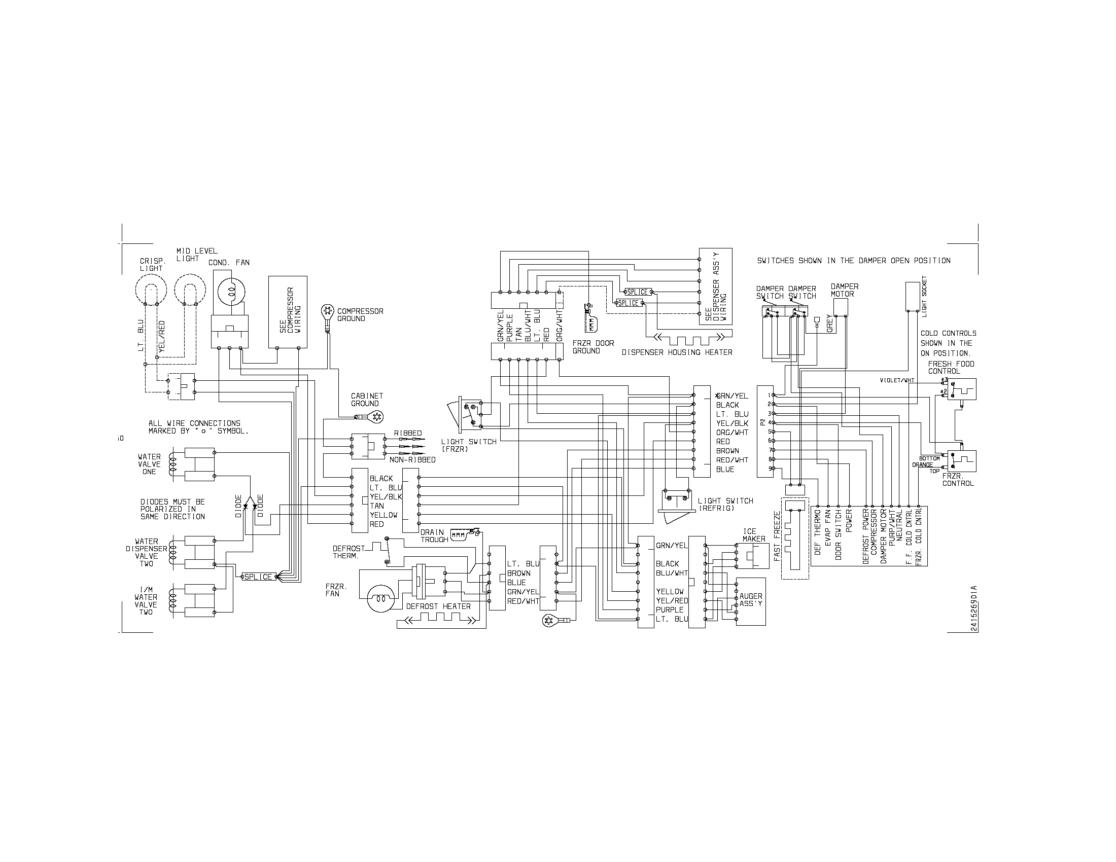
10259 Commercial Cooler Control Panel Wiring Diagram
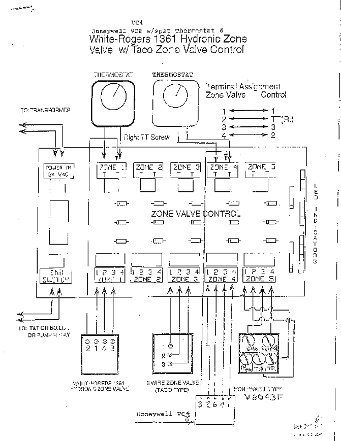
10259 Commercial Cooler Fan Control Panel Wiring Diagram

Hvac Control Wiring / Volvo 245 (1986 1987) wiring diagrams HVAC controls Carknowledge

Electrical Wiring Diagrams for Air Conditioning Systems Part Two Electrical Knowhow
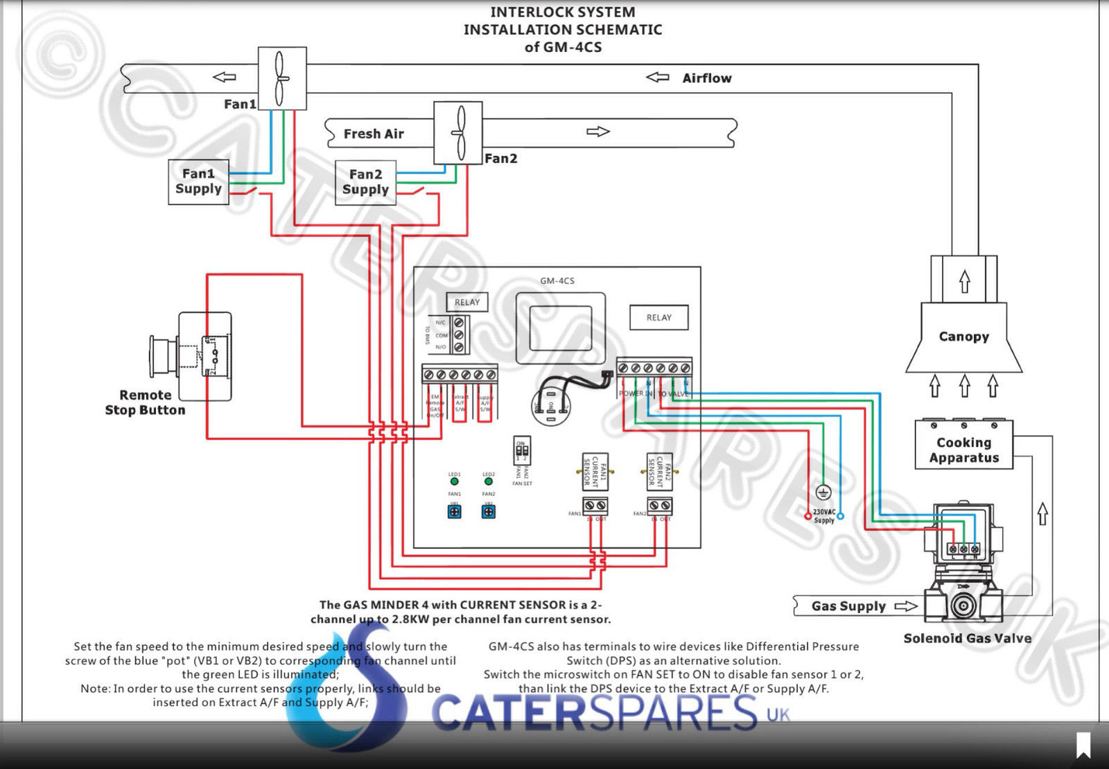
COMMERCIAL GAS INTERLOCK SYSTEM CONTROL PANEL CURRENT MONITORING CONTROLLED UNIT CaterSparesUK


